Why I Built It
In December 2022, I came across a video on YouTube in which Alan Zhao, a student at MIT, created his own DIY equatorial mount for astrophotography using a gearing mechanism called a Harmonic Drive. Since I have always been interested in outer space and astronomy, I found the idea of astrophotography quite fascinating.
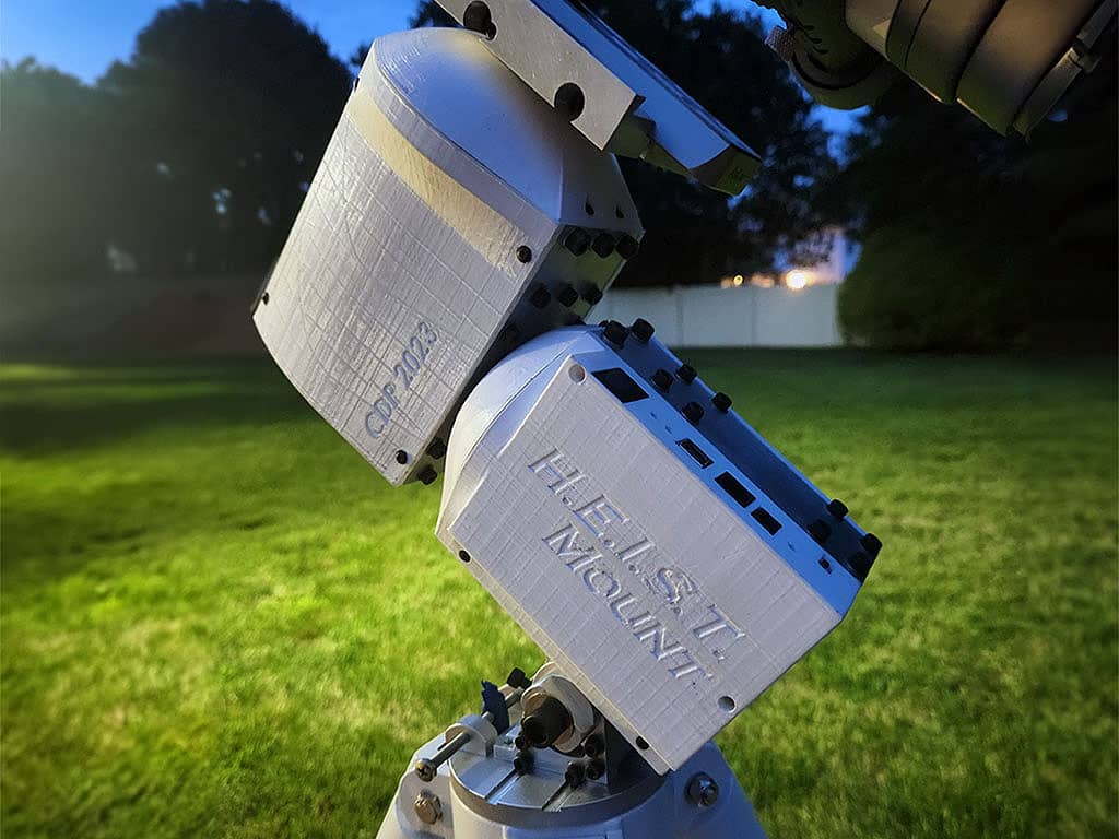
By January, I decided to design and build my own go-to equatorial mount from the ground up. Using CAD and PCB design skills I developed early on with the Harvard Satellite Team, I started a full mechanical, electrical, and software integration project and named it the H.E.I.S.T. Mount (Harvard-Engineered Imaging System and Telescope Mount).
System Goals & Design Choices
The mount was designed to be portable, powerful, and precise. The finished system has supported eight-hour imaging sessions with sub-arcsecond RMS tracking performance.
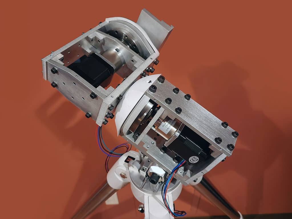
- Harmonic drives (strain-wave gearing) drive a heavy payload with minimal backlash and without counterweights.
- Open-source control compatibility keeps the electronics compatible with OnStep, an open-source telescope control system.
- Integrated custom hardware combines machined aluminum structures, 3D-printed housings, and a custom PCB around a Teensy 4.0 controller.
This project was financially supported by the NECTAR Funding program of Harvard SEAS.
High-Level Architecture
At a system level, the mount combines:
- Mechanical: equatorial mount structure + harmonic-drive gearing + stepper motors
- Electronics: a custom PCB providing power distribution, motor drive, and I/O
- Embedded control: Teensy 4.0 microcontroller running the control firmware stack
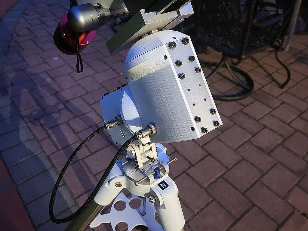
- Interfaces: USB-B for PC connectivity and ST-4 port for autoguiding
Build Process (Mechanical)
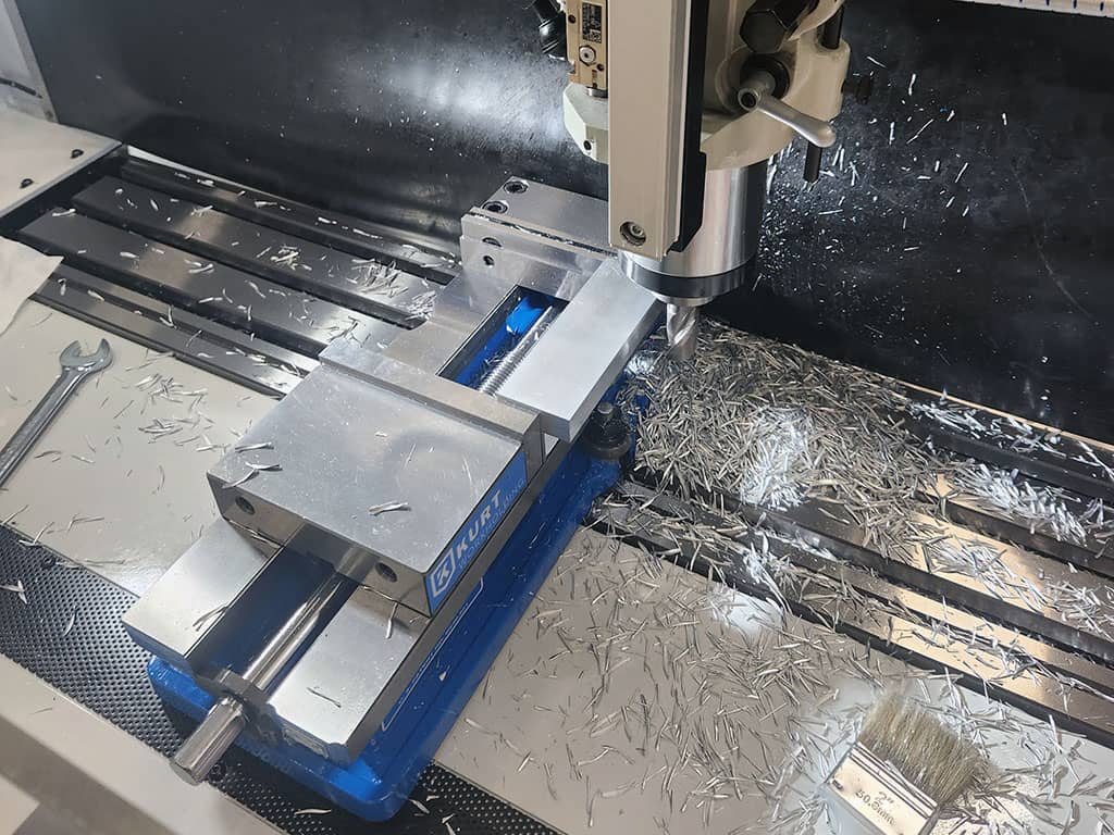
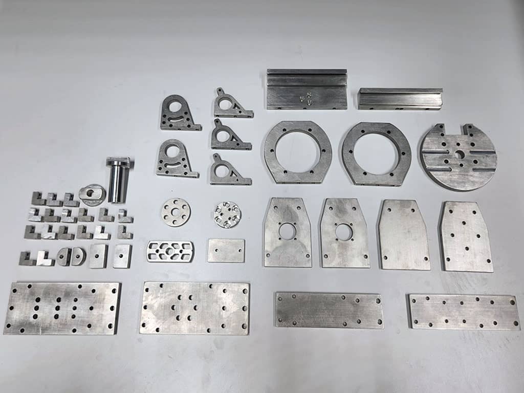
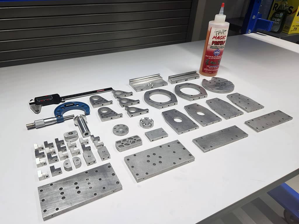
To simplify manufacturing while keeping stiffness and durability, most metal parts were designed to be cut from 6061 aluminum on a waterjet. Two components (the dovetail clamp and an altitude lock knob) were manually machined on a mill and a lathe.
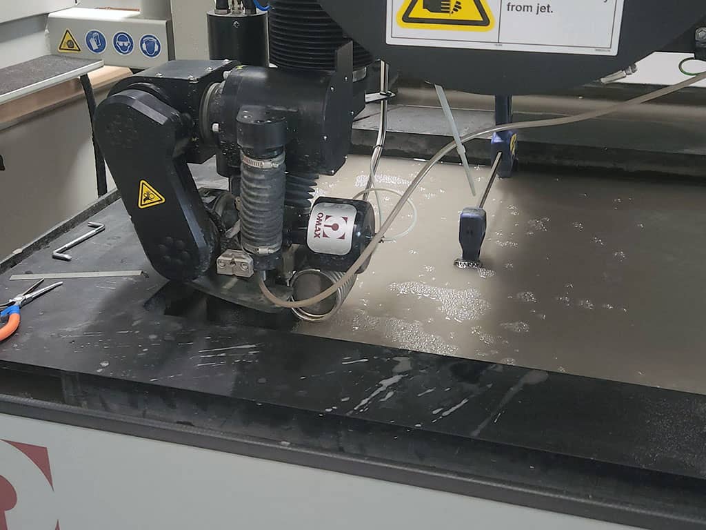
This was my first time using a waterjet machine, and it was a great learning experience, especially around process constraints, fixturing, and post-processing. The OMAX software was fairly intuitive, and the machine itself ran very smoothly.
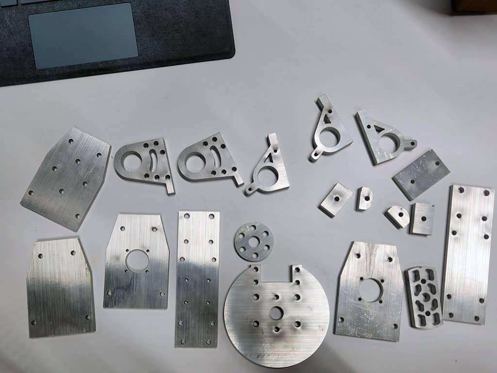
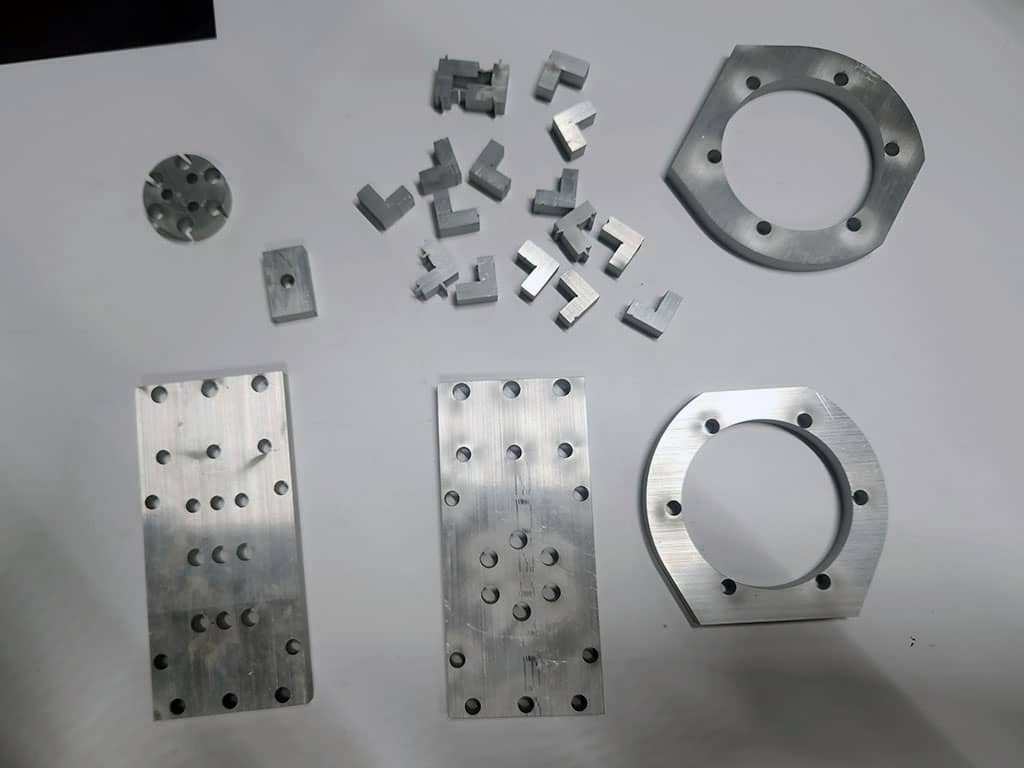
After cutting, the parts required drilling/tapping for side holes, followed by deburring/sanding.
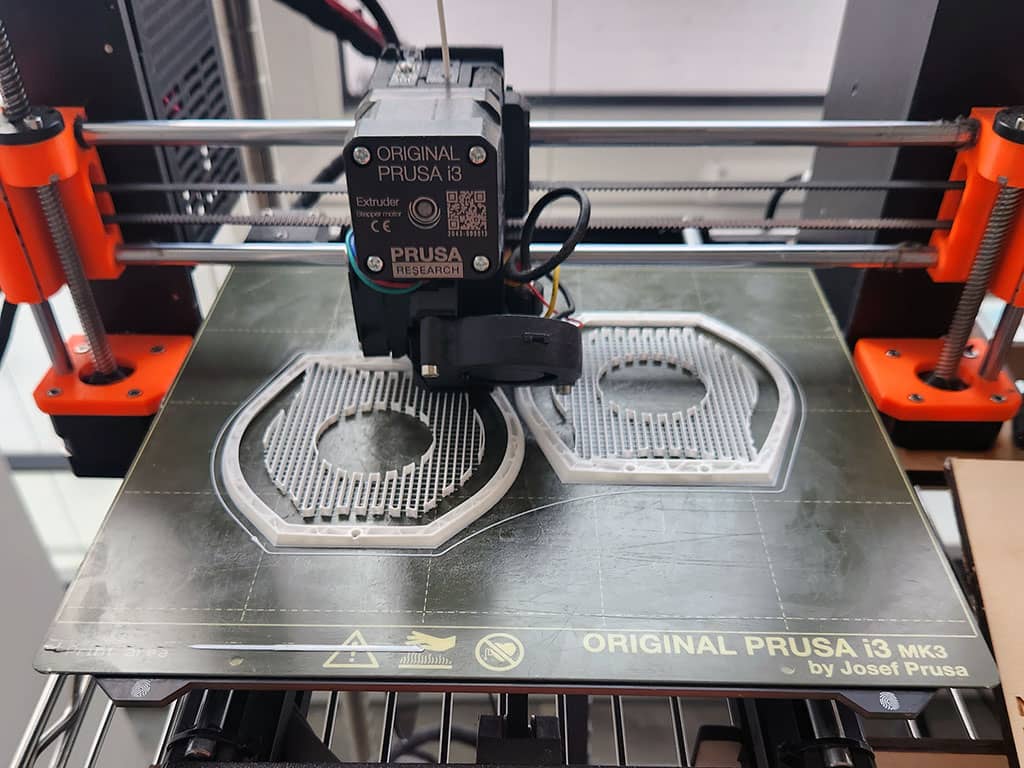
To complete the mechanical system, I 3D-printed the remaining enclosures on a Prusa i3 MK3.
Build Process (Electronics & Embedded Control)
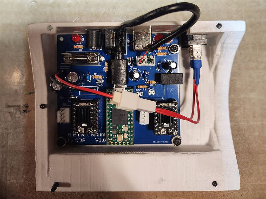
The electronics were built around a custom PCB and a Teensy 4.0 microcontroller.
- Power: 24V input powering the board and motors
- Motor drive: two TMC2130 stepper drivers
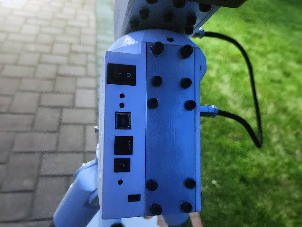
- I/O: USB-B for PC control + ST-4 for autoguiding
Here is the PCB after soldering and assembly in the 3D-printed enclosure:
Before final assembly, I tested the electronics to validate power distribution, driver configuration, and basic motor control.
Integration & Results
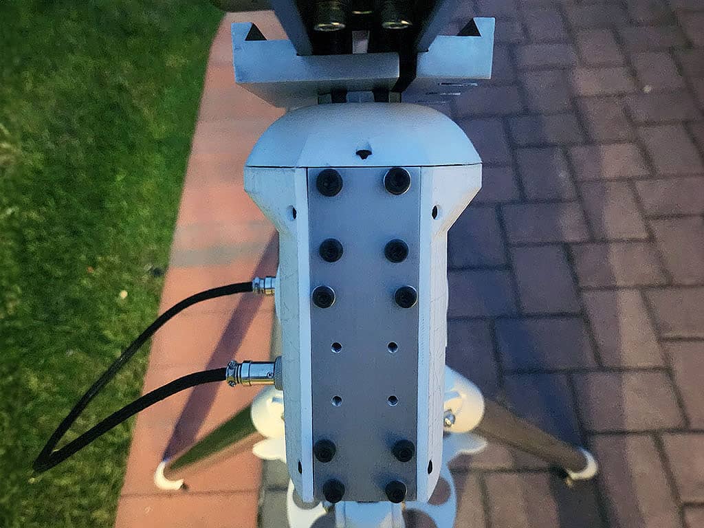
After the subassemblies were complete, I assembled the full mount and began end-to-end testing (mechanics + electronics + control).
Here is a video of the mount in action:
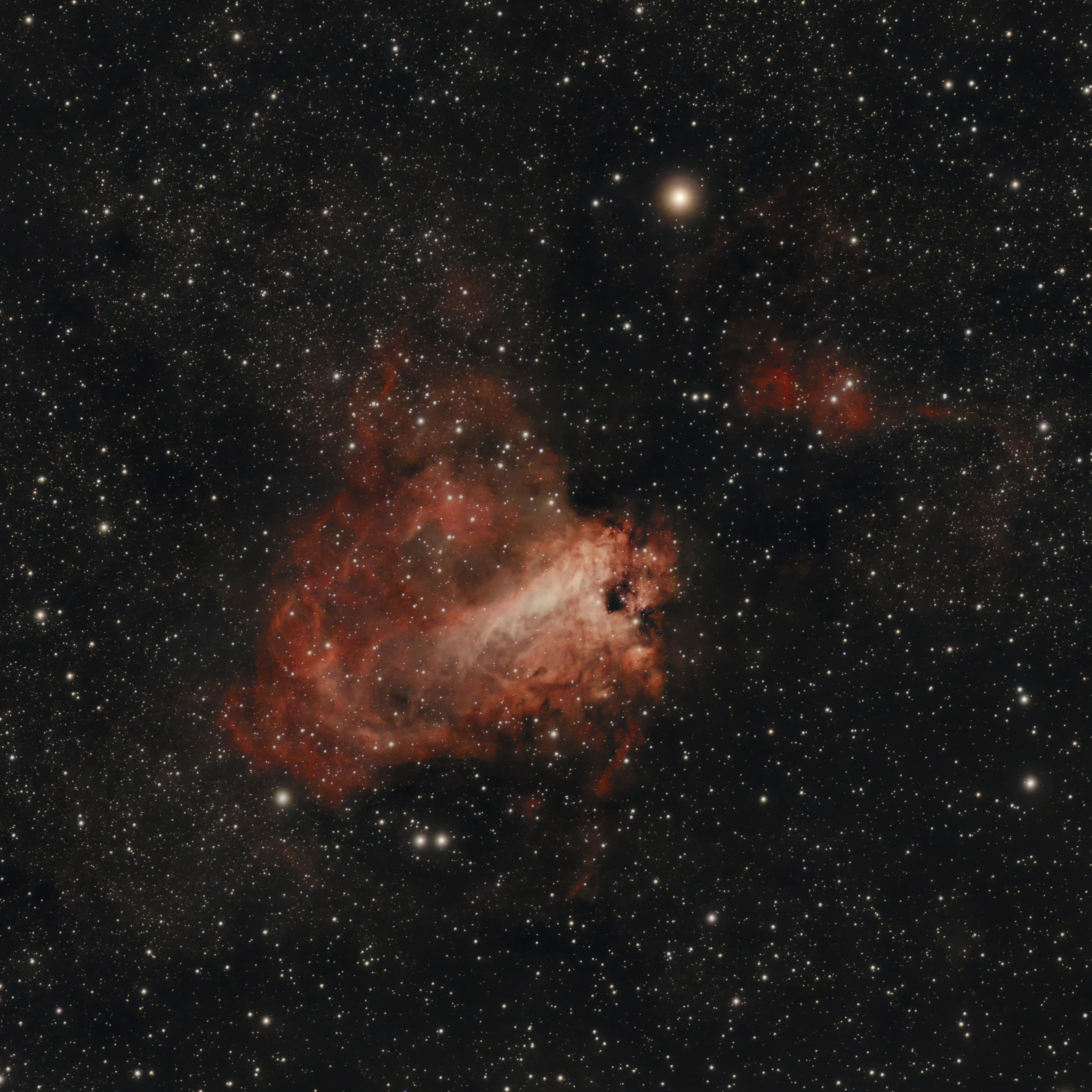
And here is the first image I captured using the H.E.I.S.T. Mount, my Askar V telescope, and a ZWO ASI533MC-Pro camera: a stacked image of Messier 17 (Omega Nebula).
You can check out more astrophotography results in the astrophotography gallery!