The IceCube Neutrino Observatory detects neutrinos with 5,160 optical modules frozen into the ice at the South Pole. Once a module is lowered into its borehole, nobody can get it back, so it has to be characterized thoroughly beforehand. I designed a facility for the next generation of IceCube modules that does this using cosmic-ray muons, which arrive at the Earth’s surface continuously.
This was my senior thesis in Prof. Carlos Argüelles’s group at Harvard. It won the Thomas T. Hoopes Prize, and you can read it on Harvard’s DASH repository.
The idea
A module under test sits in a tank of water. When a muon crosses the water, it emits a cone of Cherenkov light. If we know exactly where the muon went, we can predict how much light the module should see from that direction and compare it with what it actually recorded. The catch is that any error in the muon’s reconstructed path looks like an error in the module’s response, so the tracking has to be good.

Tracking without a dense tracker
The obvious way to track a muon is to cut the scintillator into many small tiles. I proposed reading light at both ends of larger tiles instead. The tiny difference in when the light reaches each end tells you where the muon crossed the tile, so you get position resolution without all the channels.
To find out whether that would work, I wrote a Geant4-based simulation and analysis framework (TankSim, with cosmic-ray muons from the CRY library and ROOT for analysis). I ran 180 tile and layer configurations, then reran the best ones at 200,000 events each.
What the simulation said
The main result was that timing matters more than tile size. Reconstruction falls apart once the electronics add more than about 200 picoseconds of timing jitter, no matter how fine the tiles are.
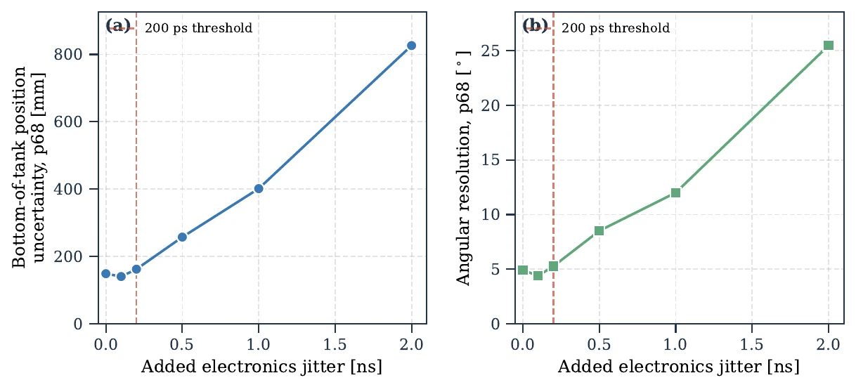
That turned a vague goal into a hard requirement for the electronics. The practical baseline is three layers of 3 × 3 tiles (200 mm EJ-200 scintillator, 54 silicon photomultiplier channels). In simulation, it reaches 4.56° angular resolution and 145.5 mm position uncertainty at the bottom of the tank.
Readout electronics
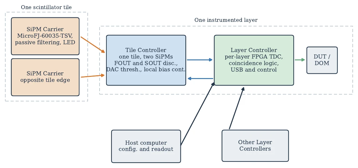
I then designed the electronics around that 200 ps budget. The system has three custom boards:
- SiPM carrier: mounts the silicon photomultiplier at each tile edge.
- Tile controller: fast discriminators, programmable thresholds, and local bias control for one tile.
- Layer controller: an FPGA-based board with a time-to-digital converter that timestamps the pulses and handles coincidence logic.
Status
The boards are in final manufacturing, and commissioning of the hardware is the next step. I’m still working on this with the Harvard group after graduating.